ESP32
The original model with dual-core processor and wide range of peripherals
- Processor
- Dual-core
- Up to 240 MHz
- SRAM
- 520 KB
- + 16 KB (divided into RTC FAST and RTC SLOW) RTC SRAM
- GPIO
- 34
- programmable pins
- Architecture
- Xtensa
- Xtensa® LX6 dual-core 32-bit
Official development kit
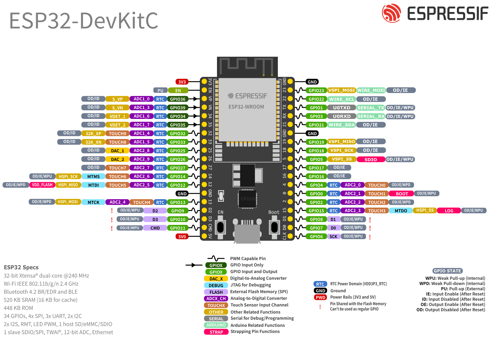
Official Espressif board for the ESP32 series.
Pins with usage restrictions
Not every pin on the ESP32 is free for general-purpose use. 17 of them have conditions: occupied by memory, sampled during boot, or function as input only. Check before finalizing your schematic.
Connected to flash/PSRAM memory
8 pins- GPIO16
- GPIO17
- SD_DATA_2 · GPIO9
- SD_DATA_3 · GPIO10
- SD_CMD · GPIO11
- SD_CLK · GPIO6
- SD_DATA_0 · GPIO7
- SD_DATA_1 · GPIO8
Already connected to the memory where firmware is stored and executed. Using them as general-purpose GPIO typically crashes the chip or corrupts execution. In modules with internal flash, they are not brought out to the package pins.
Strapping pins (boot mode)
4 pins- MTDI · GPIO12
- MTDO · GPIO15
- GPIO2
- GPIO0
The chip samples the logic level of these pins during reset to determine the boot mode. You can use them after booting, but external circuitry must not force the wrong level during reset, or the board will fail to boot or enter download mode unexpectedly.
Flashing and debugging
6 pins- MTMS · GPIO14
- MTDI · GPIO12
- MTCK · GPIO13
- MTDO · GPIO15
- U0RXD · GPIO3
- U0TXD · GPIO1
These are the flashing UART and JTAG lines. They can still be used as GPIO, but reusing them removes the ability to flash and debug the board without disconnecting connected peripherals.
Must not float
1 pin- CHIP_PU
Require a defined hardware logic level: external pull-up or RC delay circuit. Leaving them floating causes random resets or unstable boot behavior.
These groups are derived from the same data as the pinout diagram. There you can see every pin's full functions, power domain, and complete engineering notes.
Open pinout diagramProcessor
- Architecture
- Xtensa® LX6 dual-core 32-bit
- Cores
- 1 (Single-core) or 2 (Dual-core)
- Frequency
- Up to 240 MHz
- ULP Coprocessor
- Yes
- AI Accelerators
- No
Connectivity
- Wi-Fi
- IEEE 802.11 b/g/n (2.4 GHz, up to 150 Mbps)
- Bluetooth
- Bluetooth 4.2 BR/EDR (Classic) and Bluetooth LE (dual mode)
- Zigbee/Thread
- No
- Matter
- No
- Ethernet
- Yes (Integrated Ethernet MAC)
- CAN
- 1 (CAN 2.0, TWAI®)
Tools and availability
- Minimum ESP-IDF
- Since initial release (v3.x and earlier)
- Arduino Core
- Yes (147 board definitions in official core)
- Debugging
- External JTAG (requires probe, e.g. ESP-PROG)
- Package
- QFN48 (6×6 mm) and QFN48 (5×5 mm)
- Available Modules
- ESP32-MINI-1, ESP32-PICO-MINI-02, ESP32-PICO-V3, ESP32-PICO-V3-02 and 11 more
Security
- AES
- AES-128/192/256
- SHA
- SHA-1/256/384/512
- RSA / MPI
- Yes (RSA/MPI up to 4096 bits)
- ECC (elliptic curves)
- No
- Hardware ECDSA
- No
- HMAC
- No
- Digital Signature (DS)
- No
- Key Manager
- No
- Random Generator (TRNG)
- Yes (hardware TRNG)
- Flash Encryption
- Yes (AES-256, legacy scheme)
- Secure Boot
- V1 (AES, legacy); V2 (RSA-3072, RSA-PSS) starting from rev v3.0 (ECO3)
- DPA Protection
- No
Memory
- SRAM
- 520 KB
- RTC SRAM
- 16 KB (divided into RTC FAST and RTC SLOW)
- ROM
- 448 KB (for boot and core functions)
- External Flash
- Up to 16 MB via QSPI
- External PSRAM
- Up to 8 MB via QSPI (in specific modules such as WROVER)
Power consumption
Typical values at 3.3 V and 25 °C. Actual power consumption depends on radio duty cycle and configured clock frequency.
- Active (CPU 240MHz)
- 30-68 mA
- Active (Wi-Fi TX)
- 180-240 mA
- Modem Sleep
- 20-44 mA
- Light Sleep
- 0.8 mA
- Deep Sleep
- 10-150 µA
- Hibernation
- 5 µA
Peripherals
- GPIO
- 34
- ADC
- 2x 12-bit SAR ADC, up to 18 channels
- DAC
- 2x 8-bit DAC
- Touch
- 10 capacitive channels
- UART
- 3
- SPI
- 4 (SPI, HSPI, VSPI - 2 can be used for Flash/PSRAM)
- I2C
- 2
- I2S
- 2
- PWM
- LED PWM (up to 16 channels), Motor PWM
- USB
- No
Special interfaces
- SDIO
- 1 (SD/SDIO/MMC Host), 1 (SDIO/SPI Slave)
- Hall Sensor
- 1 (internal)
- Temperature Sensor
- No (removed from datasheet in 2018; no driver in ESP-IDF)
Temperature limits
- Operating
- -40°C to 125°C
- Storage
- -40°C to 150°C
Ready to prototype with ESP32?
Explore development boards available for this series, with USB, onboard sensors, and official store links.